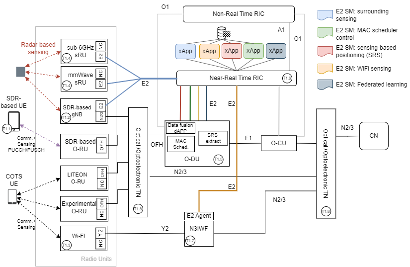
PoC #1 — Multi-Technology ISAC Platform
In this PoC, we will build an end-to-end small-scale proof-of-concept prototype to demonstrate performance and energy efficiency of Integrated Sensing and Communication (ISAC) in a form of an operated RU, DU, and CU/UPF pools with a real-time control fabric providing sub-millisecond control loop over each network component.
The PoC includes the following components:
1) a Service Management Orchestrator (SMO) will be used to facilitate validation and experimentation
and provide reproducibility;
2) a network of multi-technology RUs are connected to the OAI-based disaggregated RAN and CN network functions in a form of container images;
3) real-time control fabrics enriched with five ISAC control logics including spectrum management, RAN sensing, RAN monitoring, RAN control, and user positioning enhanced with CN location management functions (LMF) deployed as edge applications, i.e. xApps; and
4) 5G optimized compute nodes all synchronized using IEEE 1588v2 Precision Time Protocol (PTP). These components are represented in the figure.
The envisioned PoC is unique in that it is an end-to-end real-world testbed exhibiting 6G ISAC capabilities. We will experimentally measure and assess the performance and energy improvement in different deployment scenarios up to the TRL 4 considering different user spatio-temporal connectivity and traffic patterns.
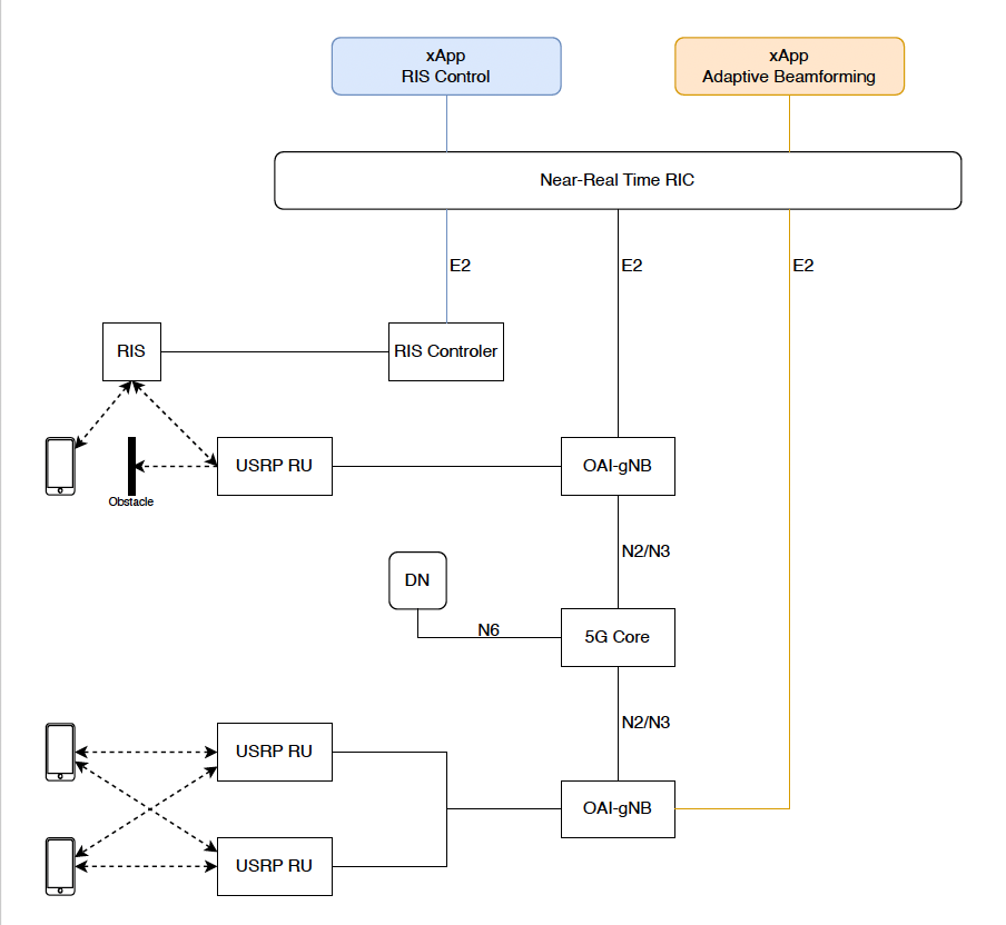
PoC #2 — 6G CF-mMIMO PHY prototype
Based on the previous figure, and leveraging the capabilities of a set of WATs in the RU Pool, i.e. Sub-6 and mmWave devices, we deploy a 6G CF-mMIMO PHY prototype and extend it to support real-time control loop (Figure on the right). The proposed prototype comprises of the Sub-6 and mmWave APUs. Additionally, it comprises the following components:
– BS and UE cf-mMIMO PHY layer able to establish a data plane and expose interfaces to be monitored and controlled.
– RAN RT control fabric enabling realtime RAN sensing, and control.
– Edge applications providing logics for RAN sensing, and controlling, e.g. instructing each AP to be active or passive (on/off strategy similar to phantom cells)
PoC #3 — Network Digital Twin (NDT) via RAN Sensing
PoC#3 implementation is depicted in the figure on the right. The setup is divided in three main entities, i) the Real Network in the bottom right, ii) the Common SMO in the upper part, and iii) the NDT in the bottom left. The Real Network is the one defined in the lab of UC where CU/DU/RU are implemented. This one is connected with the Common SMO that collect the telemetry provided via the O1/A1/O2 and Y1 interfaces. The near RT RIC aims to provide the telemetry information toward the SMO Data enrichment subsystem. This entity collects the data via O-RAN standardised interfaces. Inside the Common SMO, the NDT manager system provides the elements to control the NDT. First, the model monitoring is in charge of collecting data from the SMO data enrichment and organise in usable pieces to create usable models, they can be in the form of configuration files or real network entity representations depending on the description of the NDT itself.
The models created by the model monitoring are stored on the Model Database. The model management organises them and evaluates how close the models are to the real network via evaluation of KPIs. Additionally, the model management defines which models are sent to the NDT via the model serving entity. The third part, the NDT is composed by the ns3 5G-LENA network level simulator that is integrated with Sionna RT and on the field data from OTE 5GS UE and Open 5G SNPN. They are controlled by the model manager which determine the configuration files for each setup and triggers the simulation with the configure values. Results of the simulation are returned to the model management to model evaluation and improvement.
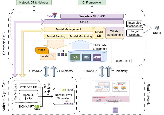
The yellow part of the SMO, i.e., the Model Monitoring, Management, Serving and Database, are the foundation for the creation of an NDT. They oversee creating a replica of the real network and evaluate the accuracy of this replica based on defined KPIs. These elements satisfy the requirement of creating NDT that represent the real network. Still, this is an instantaneous observation of the real work that does not provide update or evaluation of how the real network is evolving or changing. To tackle this, the purple entities handle the Continuous Integration and Continuous Deployment (CI/CD) of the models. They are set as the feedback loop of the NDT to optimise the accuracy of the model via AI techniques. To achieve this, an MLRun serverless mechanism is implemented to continuously look for deviations of the model results and, intelligently, modify network parameters to deploy up-to-date models into the NDT. A clear continuous cycle between the model management and the CI/CD entity is the interconnection between them.
In addition, to use the NDT to evaluate possible changes in the configuration to optimise the network performance, the “what-if” manager is introduced. In this way, optimisation objectives, such as energy efficiency, are evaluated in a sand-box. The same infrastructure of the NDT can be used as a sand-box to evaluate the optimize-to-be configurations. In this way, the “what-if” manager defines network configurations that have the chance to optimise towards a predefined objective. Hence, a set of configurations are sent to the model manager to fire a specific network configuration in the NDT sandbox, and evaluate the results with the objective KPIs. The “what-if” manager then evaluates which is the best configuration and selects the one with the best performance. Then, this configuration is applied to the real network to achieve the desired optimisation goal.
Finally, a user dashboard is presented to show the network and NDT KPIs, and the capabilities to define the “what-if” objectives and how they are selected.
